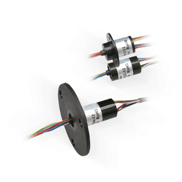
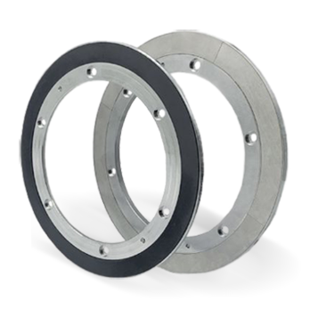
Slip Ring | 24 circuits | SVTS C 03-T-A-00/24
Through hole, I.D. 12.7 mm, O.D. 54.0 mm, 6 to 24 circuits
![Slip rings [commerce_product:title] the best way for your project](/sites/default/files/products/slip_rings/svts-c-03-t-a-0024.webp)
Slip ring for transmission of electrical power and/or electrical signals with through hole for shaft or rotary union. High data rate up to 100 Mbits/s.
The SVTS C 03 series is charaterized by a through hole and uses a special technology.
It allows to get multiple contact points between brushes and rings, low contact electrical resistance, reduced noise and low wear. No lubrication required. These slip rings are available in IP51, IP54 or IP65 and offer many customization possibilities.
Advantages
- Ideal for electrical power and signal transmission
- Through hole 12.7 mm
- High data rate
- Low friction torque
- High lifetime and reliability
- Compliant to CE and ROHS
Benefits
- Transmission of electric power/signals and fieldbuses in one unit
- Mountable on the shaft mitigating the need of interface parts
- Combinable with fluidic rotary joints and FORJ
- Cost-effective


