
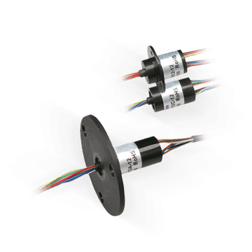
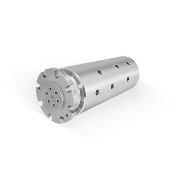
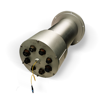
Slip Ring | 24 circuits | SVTS C 07-U-A-00/24

Through hole, I.D. 60.0 mm, O.D. 135.0 mm, 6 to 96 circuits and more

Slip ring for transmission of electrical power and/or electrical signals with through hole for shaft or rotary union.

The SVTS C 07 series is charaterized by a through hole and uses a special technology.

It allows to get multiple contact points between brushes and rings, low contact electrical resistance, reduced noise and low wear. No lubrication required. These slip rings are available in IP51, IP54 or IP65 and offer many customization possibilities.

Advantages

  • Ideal for electrical power and signal transmission
  • Through hole 60 mm
  • High data rate
  • Low friction torque
  • High lifetime and reliability
  • Compliant to CE and ROHS

Benefits

  • Transmission of electric power/signals and fieldbuses in one unit
  • Mountable on the shaft mitigating the need of interface parts
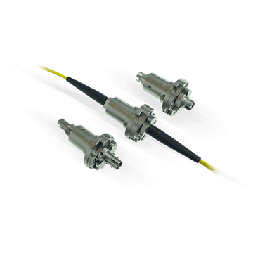
  • Combinable with fluidic rotary joints and FORJ
  • Cost-effective

SVTS C 07-U-A-00/24
Circuits 24 x 5A
Outside Diameter 135.0 mm
Inside Diameter 60.0 mm
Overall Length (L) 110.5 mm
Protection rating IP 65
Data Transfert <=100Mbit/s
Mounting Thru-bore 60mm

Mechanical features

Nominal speed >400 rpm
Temperature range -20°C to +80°C (-40°C as option)
Contact gold-gold (alloy)
Bearings Miniature high-precision stainless steel ball bearings
Connector -
Mounting ABS

Electrical features

Voltage 600 VDC/VAC,240VDC/VAC
Cables Silver plated / PTFE insulated / colour coded
Cables length 250 mm standard (other length on request)
Dielectric voltage strength 500VAC @ 60Hz @ 60 sec
Insulation resistance >500MOhm/500VDC
Dynamic contact resistance <10mOhm @ 6VDC and 500mA (@ 5rpm)
Expected lifetime 107 revolutions (depending on speed, environmetal conditions and size)

Customisations

  • Cables
  • Materials
  • Mechanical design
  • Flange

Notice : The provided technical data are the higher limits recommended in static condition. To obtain the correct dimensioning of the product, it is necessary to hold account of all the applicable dynamic forces, including the inertia of the manipulator, the configuration of the tools and the external forces applied.

Drawings
Steps